
Water Consumption in Indirect-Direct Evaporative Cooling (IDEC) Systems
QUICK READ
AI summary
Understanding Water Consumption in Two-Stage IDEC Systems. Indirect-Direct Evaporative Cooling (IDEC) systems cool large industrial spaces in two distinct stages: an indirect stage (IEC) that cools primary air without adding moisture, and a direct stage (DEC) that cools air further through direct water evaporation. Total water demand-known as make-up water-goes beyond evaporation alone, factoring in bleed-off for mineral control, drift, and routine sump maintenance. Accurately estimating annual water usage requires hourly weather modeling alongside energy performance rather than relying on single peak-hour figures.
In evaporative cooling, the heat transferred from the air being cooled is used to evaporate water. These systems often handle large volumes of outdoor air in factory sheds and other industrial buildings with substantial ventilation or exhaust requirements. Water takes management and incurs costs. This raises an important question: how much water does an Indirect-Direct Evaporative Cooling (IDEC) system use?
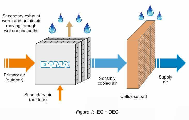
Water use in IDEC systems
An IDEC system cools the primary, or supply, air in two stages. In the Indirect Evaporative Cooling (IEC) stage, a separate secondary air stream is cooled by evaporation and removes heat from the primary air through a heat exchanger. The primary air is sensibly cooled without gaining moisture. In the direct evaporative cooling (DEC) stage, water comes in direct contact with the primary air and evaporates into it, producing further cooling. This process converts a part of its sensible heat into latent heat.
The total make-up water required by the system has four main components:
Make-up water = evaporation + bleed-off + drift or carryover + cleaning and sump losses
Make-up water is the fresh water supplied to replace these losses.
The water circulation rate through pumps and distributors should not be confused with water consumption. In cross-flow plate-type heat exchangers such as the DAMA®, the water circulation rate exceeds the water evaporation rate, and most of the circulated water returns to the sump.
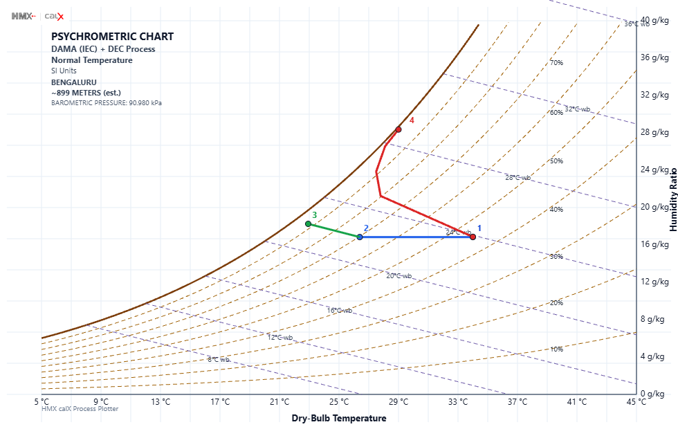
Figure 2: Schematic of the IDEC process on a psychrometric chart. Outside air (1) is sensibly cooled in the IEC till point (2) and further cooled by DEC till (3). Under conditions of the test, the path followed by the secondary air in the IEC is denoted by 1‒4. The quantity of secondary air is 35% of the quantity of the product air.
Water evaporation in the IEC stage
In the IEC heat exchanger, water evaporates into the secondary air stream The most direct air-side estimate is therefore based on the increase in its humidity ratio. In HVAC practice, this is also commonly referred to as absolute humidity:
Water evaporated = dry-air mass flow of secondary air x (outlet humidity ratio – inlet humidity ratio)
Humidity ratio is the mass of water vapour carried per unit mass of dry air. The rate of water evaporation depends on the flow of secondary air, inlet air condition, heat exchanger design, and water distribution and should therefore be established from validated performance data or model.
KEY INSIGHT
Most water evaporates in the indirect stage without humidifying supply air
In a typical 52,000 m³/h IDEC unit, the Indirect Evaporative Cooling (IEC) stage consumes roughly 210 L/h of water compared to 72.4 L/h in the Direct Evaporative Cooling (DEC) stage. This insight highlights that while the indirect stage drives nearly 75% of total evaporation (4.03 g vs. 1.39 g per kg of product air), it keeps that moisture isolated in a secondary exhaust stream-delivering 7.8 K of sensible cooling without adding humidity to the conditioned indoor space.
Water evaporation in the DEC stage
In the direct stage, the water evaporated can also be found from the increase in humidity ratio of the supply air (refer to same figure above). Alternatively, a first estimate can be made from the cooling achieved:
Water evaporated ~ evaporative cooling delivered/latent heat of evaporation of water
This is an approximation because the fan heat, heat gain through the casing and other equipment-related losses may affect the balance.
As an illustrative example, the table below lists the psychrometric properties of air of the 4 different points in Figure 2.
Table 1. Psychrometric properties at each state point in Figure 2.
|
State point |
DBT (°C) |
RH (%) |
Humidity ratio W (g/kg dry air) |
Enthalpy h (kJ/kg dry air) |
|
1 Inlet / ambient (primary = secondary) |
34.0 |
45.1 |
16.8 |
77.4 |
|
2 IEC outlet (primary) |
26.2 |
70.0 |
16.8 |
69.0 |
|
3 DEC outlet (primary) |
23.2 |
90.5 |
18.1 |
69.4 |
|
4 Secondary exhaust (IEC) |
29.0 |
99.0 |
28.4 |
101.6 |
Based on the above, the rate of water evaporation in an IDEC machine of 52,000 m3/h capacity is approximately 210 l/h in the IEC section, and approximately 72.4 l/h in the DEC section.
Quantity (basis: 1 kg product air; secondary = 0.35 × primary)
| IEC stage | DEC stage | Total (IDEC) | |
| Cooling, ΔT (K) | 7.8 | 3.0 | 10.8 |
| Water evaporated (g / kg product air) | 4.03 | 1.39 | 5.42 |
The IEC stage typically evaporates more water than the DEC stage, both per unit of cooling and in total, but no water is added to the product air unlike the DEC where all the water is added to the product air.
IMPORTANT OBSERVATION
Water circulation rates do not equal actual water consumption
In cross-flow plate-type heat exchangers, the volume of water pumped and distributed over the media far exceeds the amount actually lost to evaporation, as the majority recirculates back into the sump. Confusing pump circulation flow with net water consumption can distort facility water budgets, which should instead be calculated from actual make-up water components: evaporation, mineral bleed-off, drift, and cleaning losses.
Bleed-off and cycles of concentration
As water evaporates, dissolved minerals remain in the circulating water and become concentrated. A controlled quantity of water is therefore discharged and replaced with fresh water. This is called bleed-off or blowdown. If C represents the selected cycles of concentration, a simplified estimate is:
Bleed-off ~ water evaporated/(C – 1)
Cycles of concentration indicate how many times the dissolved mineral content in the circulating water has increased relative to the make-up water. The permissible value depends on the make-up water chemistry, equipment materials and water-treatment plan.
Other water losses
Drift or carryover is normally small in properly designed and operated equipment but may not be zero. Water used for sump draining, cleaning, filter flushing, leakage and maintenance may be small in a continuously operated plant but can become significant where water quality is poor or equipment operates intermittently.
Estimating annual water consumption
A single design-hour value does not represent annual water consumption. Weather varies by city, season and time of day. A practical annual estimate should:
- Use reliable hourly weather data for the project location, such as a Typical Meteorological Year (TMY) file
- Apply the actual operating schedule, including any weekly and seasonal shutdowns
- Determine the operating mode for each hour: IEC only, DEC only, or combined IDEC operation
- Calculate the water evaporation for every operating hour
- Add the corresponding bleed-off and reasonable allowances for other losses to arrive at the water consumption for every operating hour
- Sum the water consumption for all operating hours
KEY TAKEAWAY
Evaluate annual water use alongside weather data and energy efficiency
A single peak design-hour calculation cannot accurately predict yearly water demand, as ambient temperature, humidity, and operating modes (IEC-only, DEC-only, or combined IDEC) shift throughout the year. Facility planners should model hourly Typical Meteorological Year (TMY) weather data against actual operating schedules-and weigh water consumption alongside total cooling delivered and electricity saved, since higher-efficiency systems often reduce overall airflow requirements and operating hours.
Consider water and energy together
At the same airflow and inlet condition, greater evaporative cooling generally requires more water evaporation. On the other hand, a more effective system may deliver the required cooling with less airflow or fewer operating hours. Thus, annual water use should preferably be assessed together with the useful cooling delivered and electricity consumed.

The Technical Team at HMX brings engineering expertise in advanced evaporative cooling, HVAC systems and energy-efficient climate-control solutions. Drawing on HMX’s product technologies, certifications and application knowledge, the author/s explain complex cooling concepts in a practical manner. Our articles cover DAMA® Heat Exchanger based IDEC + Adiabatic Cooling, Indirect Evaporative Cooling, TFA Units, Hybrid AHUs, and HVAC Systems. Technical insights address system selection, cooling performance, indoor air quality, fresh-air requirements, energy saving and application conditions. The content helps engineers, HVAC consultants, architects and facility teams evaluate technologies for their specific spaces. It is relevant to industrial and commercial applications including factories, warehouses, offices, workshops and large buildings. The expertise extends across diverse markets and practical technical guidance to support informed, efficient and application-focused cooling decisions.

